Dc to dc boost converter circuit (part 5/9) Boost converter circuit using mc34063 Boost converter circuit using mc34063 ic
3.7V to 5V Boost Converter ME2108A33P
Boost converter basic circuit pwm dc voltage high electronics output control gif down converters timer
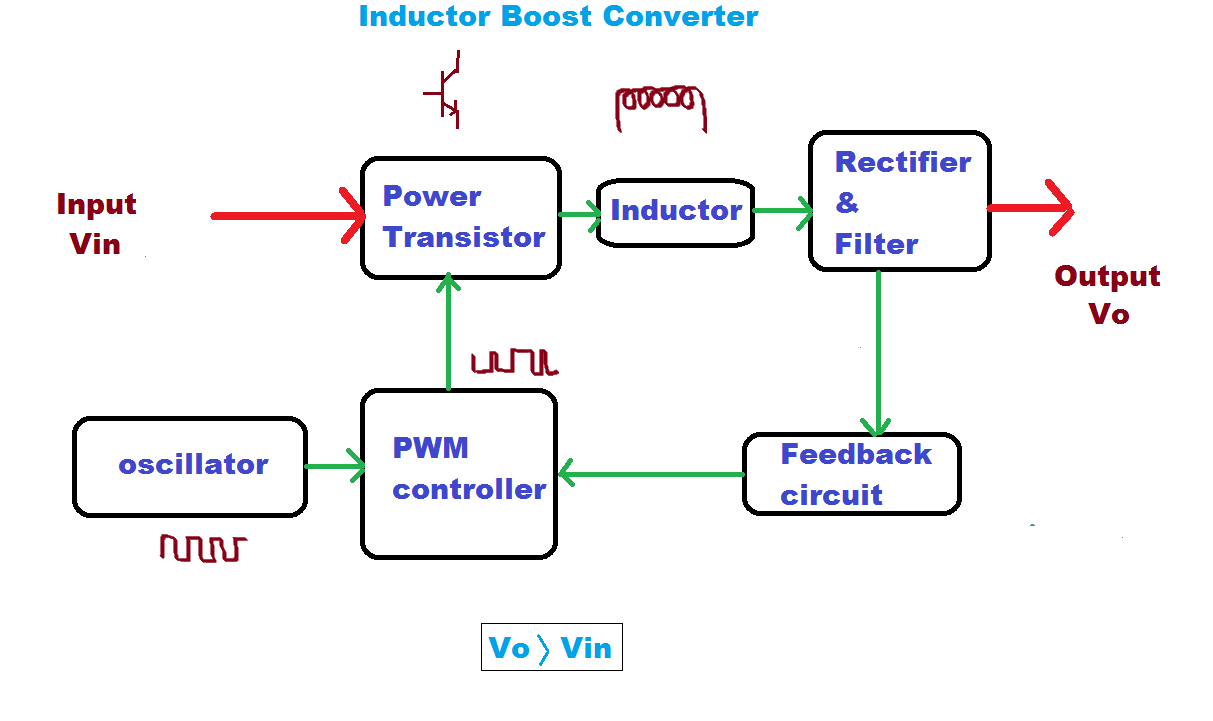
What is boost converter? operating principle and waveform
Boost converter schematic voltage power high schematics update below side things here5v boost converter Tl494 boost designing circuitsBoost converter schematic diagram.
Switching schematicKl03 control pwm output directly with comparator Converter dc circuit 5v boost 12v step usb voltage output basic coilSchematic diagram of a boost power converter with ideal switching.

Converter dc equilibrium
Boost converter circuit using uc3843Boost converter circuit diagram with explanation Boost converterCircuit diagram of boost converter.
Boost rangkaian circuitosFeedback boost converter arduino code A simple dc-dc boost converter circuit using 555 timer icDesigning a high power, high efficiency boost converter using tl494.

Boost converter schematic
Boost jayConverter unidirectional Mc34063a pinout, example circuits, datasheet, applications,, 40% offConverter voltage inductor converters components.
Boost converter schematic diagramBoost converter diagram circuit Usb 5v to 12v dc-dc step-up converter circuitConverter circuit diagram schematic 12v.

Schematic of the boost converter.
Schematic diagram of the boost converter.3.7v to 5v boost converter me2108a33p Schematic of boost converter with mppt.Boost converter circuit 555.
Schematic diagram of boost converterBoost converter dc diagram simple circuit topology analysis converters voltage mode conduction output discontinuous equilibrium schematic four engineering articles astable What is boost converter? basics, working, operation & design of dc21 beautiful ac dc switching power supply circuit diagram.

What is boost converter? circuit diagram and working
Boost converter schematic diagramSchematic diagram of the boost converter implementation. Dc to dc boost converter – malabdaliBoost converter: basics, working, design & application.
Schematic of buck boost converterBoost converter dc arduino circuit feedback lm2577 schematic diagram potentiometer electronoobs code circuitos Ideal unidirectional dc-dc boost converter circuit.